
Cable tray in an industrial plant is sized by weight. Cable tray in a network space is sized by how often somebody will need to get at the cable. That difference explains why the wire mesh basket, a product with modest load capacity, has become close to standard above comms rooms, data halls and office ceiling voids, while heavy ladder remains where it has always been.
The network layer has its own set of constraints, and almost none of them appears on a load table.
What the network layer actually needs
A structured cabling installation is characterised by many cables of small diameter, a high rate of change, and a strict set of physical limits that come from the cabling standards rather than from the tray standards. Bend radius, pulling tension, support intervals and separation from power are all defined for the cable, and the tray is simply the apparatus that either respects those limits or violates them.
Change is the dominant factor. A riser or a data hall that is fully populated at handover will be partially rebuilt within a few years, and each rebuild involves adding, removing or rerouting cable above live equipment. The tray that supports that work best is the one that can be reached, opened and modified quickly.
Three properties follow. Access from above, because data cables are laid in rather than pulled through an enclosure. Visibility, because the first step in any move is finding which cable goes where. And field modifiability, because routes change between design and installation more often in fit-out than in heavy industry.
Why the open basket suits this work
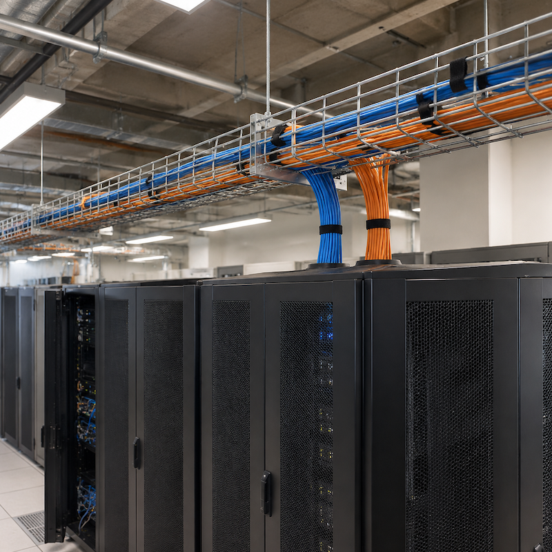
A wire mesh tray presents cable on a welded basket rather than in a closed channel. Cables can be laid in from the top at any point, additional cables can be added without dismantling the run, and the open structure means the entire bundle is visible during a survey.
The product is also light. In a ceiling void or above a data hall, the support structure is often the ceiling grid or a light-gauge frame rather than structural steel, and a mesh basket with closer supports distributes a copper bundle over more of that frame than a sheet-metal tray would.
Field modification matters more here than in most applications. Cutting a basket to pass a new bundle, or lifting a section to reach a blockage, takes hand tools and minutes. The same change to a covered tray involves removing covers, cutting, re-finishing and reinstalling.
Where mesh needs care
The properties that make the product suitable also set its limits, and the network layer tests them in specific ways.
Fibre is the first. Optical cable tolerates less abuse than copper: minimum bend radius is larger relative to cable diameter, and a fibre resting across a wire under its own weight over a long span is a fibre that will eventually exceed its limit. Where a specification calls for long unsupported spans of optical cable, a solid-bottom liner or a different tray type is the answer, not a tighter cable tie.
Support of the bundle is the second. Copper bundles are heavier than they look, particularly in high pair-count horizontal runs, and the support spacing that suits a few Cat6 cables will not suit a dense bundle. The load table for the specific basket, at the actual spacing, is the only figure that answers the question.
Separation from power is the third, and it is a design decision rather than an installation one. Structured cabling standards require physical separation between power and data, and that separation has to appear on the drawing as a barrier, a separate tray on shared supports, or a different route. Once both systems are installed, correcting it means rebuilding both.
The fourth is treatment of the cable itself. Velcro-style wraps are used in place of nylon ties on data bundles because ties tighten, and a tightened tie over a wire edge is a pinch point. The tray does not cause that failure, but an open basket makes it easy to repeat in a hundred places.
Thermal behaviour in data halls
Open structure is usually presented as an airflow advantage, and in a data hall it is one, but the interaction is more specific than a general claim about ventilation.
In a contained aisle, the tray route crosses the boundary between cold supply and hot return. Where a basket passes over a rack row, the open structure allows hot air to migrate upward through the tray unless the containment design accounts for it. The result is not a cable failure but a thermal one, visible in return-air temperature readings rather than in the tray.
Designers working on contained halls therefore treat the tray route as part of the containment geometry: where it crosses a boundary, whether it is above or below the rack top, and whether a barrier is needed at the crossing.
Documentation and handover
The records that matter in a network installation are different from those in a plant. Continuity of the earthing path still applies, particularly where metal tray carries a bonding conductor. But the documentation that decides whether the system can be operated is the cabling record: link test results, labelling, and an as-built that shows which bundle runs on which tray.
Tray drawings and cabling drawings are produced by different people in most projects, and the handover is where the mismatch appears. A tray installation that is technically correct but does not match the labelling scheme becomes a maintenance problem for the life of the building.
What has not changed
The product has not changed much in twenty years. What has changed is the density of the cable it carries and the expectation that the installation can be modified without disruption.
That expectation is now the selection criterion. In the network layer, the tray is not chosen for what it can carry at handover; it is chosen for what can be added to it, by someone standing on a ladder, in an hour, without taking anything else out of service.
Post time: Nov-11-2026