
CASTRIES, St. Lucia & SHANGHAI, China — In a major development for Caribbean infrastructure and public safety, Shanghai Qinkai Industry Co., Ltd., a leading global manufacturer and designer of industrial cable management and seismic support systems, has successfully delivered a comprehensive Seismic Support Design and Calculation Report for the prestigious St. Lucia Halls of Justice (HOJ) project.outlines the rigorous mechanical engineering, load calculations, and structural safety verifications executed for the suspended seismic support systems within the landmark legal complex. This structural certification represents a significant milestone, ensuring that the critical electrical distribution infrastructure of St. Lucia’s primary judicial facility can withstand seismic events and maintain operational continuity during emergencies.
The Critical Role of Seismic Engineering in Public Infrastructure
Modern public and institutional buildings require more than just aesthetic and basic structural integrity; they demand high-performance seismic resilience. This is particularly true for judicial, administrative, and emergency facilities such as the St. Lucia Halls of Justice, which serve as essential nervous centers for the local government. In regions prone to geological activity, the safeguarding of non-structural components—such as low-voltage and high-voltage cable trays, water pipelines, and HVAC systems—is a primary safety mandate.
During an earthquake, unbraced or poorly calculated suspended utilities can swing violently, leading to structural damage, severed electrical power, and severe hazards to building occupants. Suspended seismic support systems act as rigid anchors that control lateral and longitudinal movement, distributing dynamic loads safely back into the primary concrete structure.
To meet these demanding safety thresholds, Shanghai Qinkai Industry Co., Ltd. applied a combination of international and national structural standards. The engineering design bases for the HOJ project include:
- GB50017-2003: Code for Design of Steel Structures
- GB50009-2001: Code for Load Design of Building Structures
- JGJ145-2013: Technical Code for Post-Anchoring of Concrete Structures
- GB50303-2002: Code for Acceptance of Construction Quality of Building Electrical Engineering Projects
- 03S402 & 03SR417-2: Indoor Pipeline Supports and Installation Standards
These codes govern the material selection, allowable stress limits, safety factors, and deflection thresholds for the suspended systems, ensuring that every bracket is engineered with an exceptional margin of safety.
Technical Specifications and Bracket Assembly Design
The seismic support system designed for the St. Lucia Halls of Justice utilizes a multi-tiered suspended bracket configuration (ZJ-13 Bracket) to organize and support various classes of electrical cable trays. The design accounts for both low-voltage and high-voltage distribution networks running in parallel across the facility’s ceilings.
Cable Tray Load Parameters
The calculations are based on the following specific linear load criteria under a standard support spacing of 1.5 meters:
- Low-Voltage Cable Trays:
- 100×100 mm (12 kg/m)
- 200×100 mm (22.5 kg/m)
- 300×50 mm (20 kg/m)
- 300×100 mm (40 kg/m)
- High-Voltage Cable Trays:
- 100×100 mm (16 kg/m)
- 200×100 mm (32 kg/m)
- 300×50 mm (30 kg/m)
- 300×100 mm (55 kg/m)
- 400×150 mm (85 kg/m)
A safety factor of 1.2 is applied across all load cases to account for dynamic variances and future cabling expansions.
Structural Assembly Configuration
The primary assembly utilizes a 41×41 mm U-slot (strut channel) made of high-quality Q235 carbon structural steel, suspended via M10 screw rods and anchor bolts embedded into the concrete ceiling slab.
Below is the detailed technical assembly drawing illustrating the exact dimensions, spacing, and fastening hardware used in the ZJ-13 Suspended Seismic Support:
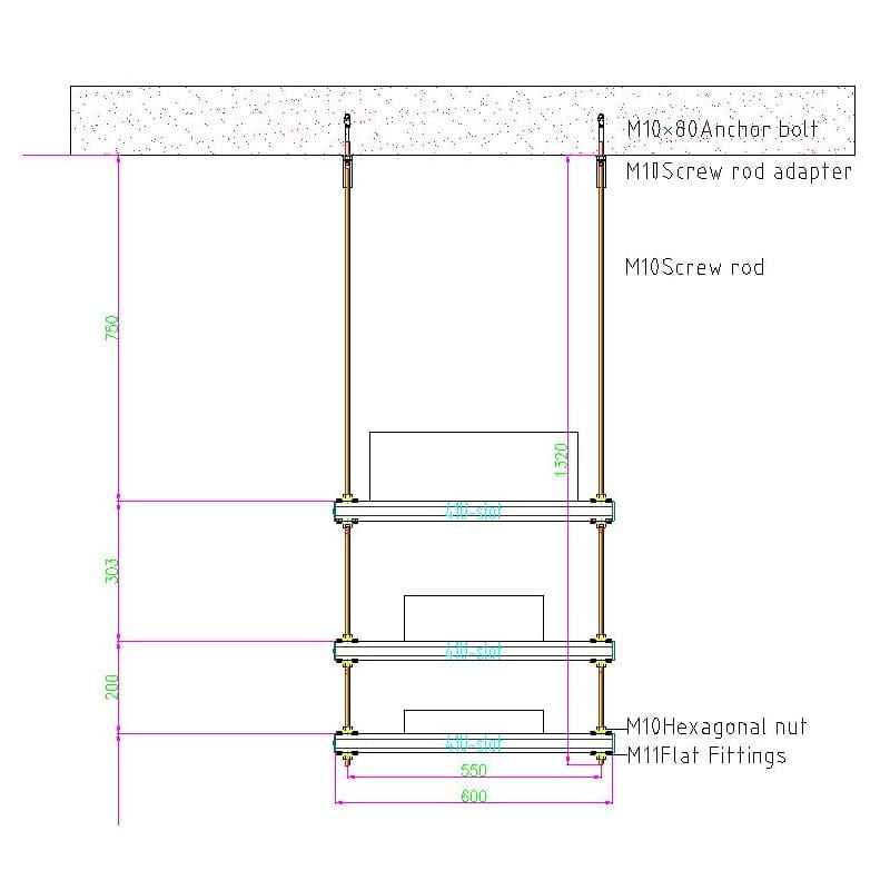
As shown in Figure 1, the suspension configuration features three tiers of 41×41 mm U-slots with a lateral span of 600 mm and suspension point spacing of 550 mm. The vertical drop is securely anchored to the concrete overhead using M10×80 concrete anchor bolts and M10 screw rod adapters. High-tensile M10 screw rods link the multiple crossbeams, which are locked in place with M10 hexagonal nuts and M11 flat fittings, providing a rigid, vibrations-resistant cage.
Material Excellence: The 41×41 mm Strut Channel Profile
The structural backbone of the Qinkai seismic support system is the 41×41 mm U-slot profile. Shanghai Qinkai Industry Co., Ltd. manufactures these strut channels from Q235 carbon structural steel, an industry-standard material celebrated for its excellent balance of tensile strength, ductility, and weldability.
Q235 Mechanical Properties:
- Gravitational Density (
ρ):
78.5 kN/m3
- Elastic Modulus (
E):
2.06×10⁵ N/mm2
- Poisson’s Ratio (
ν):
0.3
- Tensile/Bending Design Strength (
f):
215 N/mm2
- Shear Design Strength (
fv):
120 N/mm2
- End Face Pressure Strength (
sCE):
310 N/mm2
To ensure long-term durability in the humid, tropical maritime climate of St. Lucia, these strut channels are supplied with high-performance protective finishes, including Pre-Galvanized (Z275), Hot-Dip Galvanized (HDG), and Electroplated Zinc (EZ).
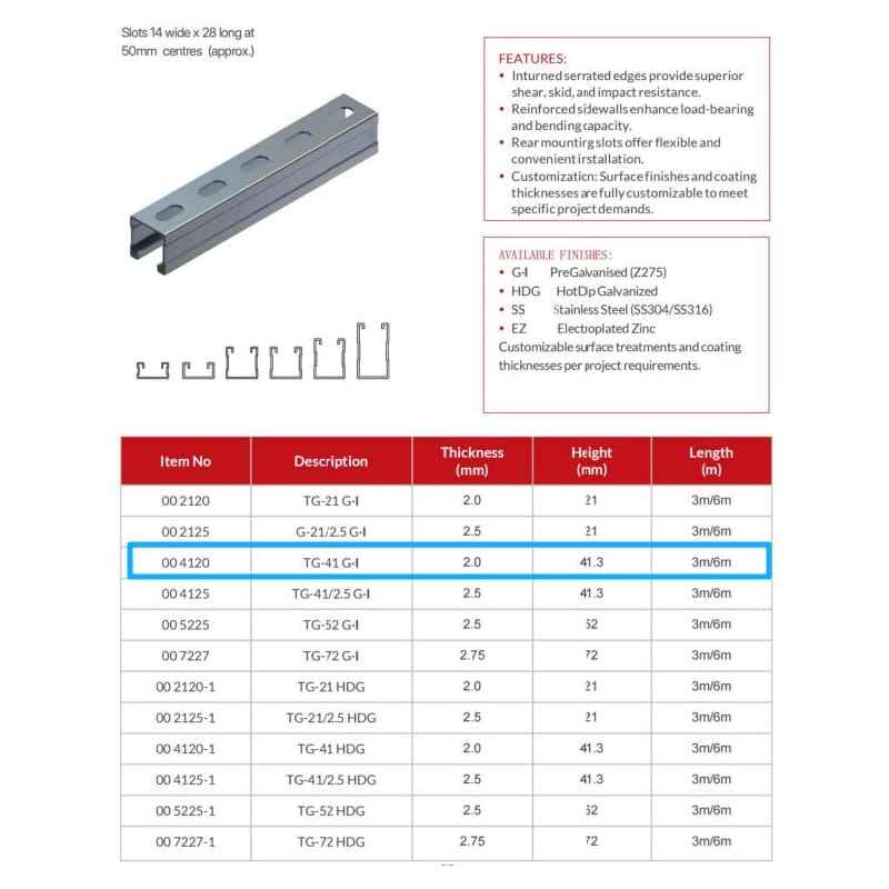
Figure 2 details the dimensional tolerances, available finishes, and mechanical product variants of Qinkai’s 41×41 mm U-slot series (Item No. 004120 / TG-41 G.I). The inturned serrated edges of the channel profile provide superior slip resistance and high shear-locking strength when coupled with channel nuts, ensuring the assembly remains rigid under seismic vibrations.
Finite Element and Structural Load Calculations
The core of the engineering report focuses on verifying that the bending stress, shear stress, and deflection of each horizontal crossbeam under maximum load are well within the allowable material thresholds of Q235 steel.
Crossbeam 1 Load Analysis
Crossbeam 1 supports the heaviest load combination, holding the high-voltage 400×150 mm cable tray.
- Factored Distributed Load:
85 kg/m×1.5 m×10 N/kg×1.2≈1.53 kN
- Bending Moment: The maximum bending moment (
Mmax) experienced by the beam is calculated at
124 N⋅m.
- Support Reaction Forces: The vertical reaction forces at the left and right suspension points are
0.756 kN each.
Structural Bending and Deflection Verification
Using beam theory, the maximum bending stress (
σ) is checked against the design strength of
215 N/mm2. The calculations demonstrate that the bending stress is highly safe.
Furthermore, beam deflection must be limited to prevent structural sagging and cracking of nearby finishes. The maximum allowable deflection under seismic load is typically
L/200 (where
L is the span). For a
550 mm span, the allowable deflection is
2.75 mm.
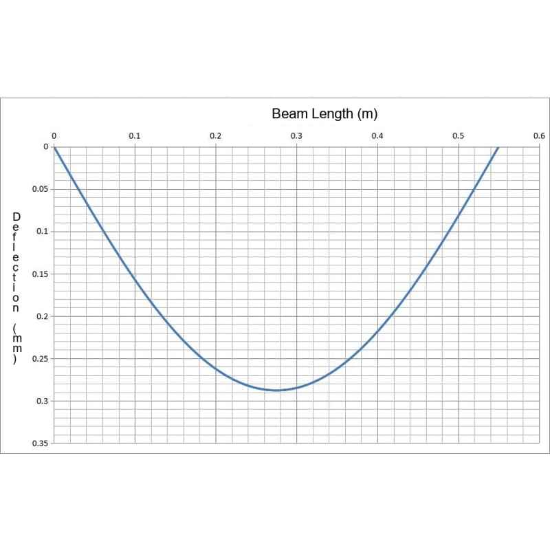
As demonstrated in the finite element deflection curve in Figure 3, the maximum deflection under full load occurs precisely at the mid-span of the beam (
0.275 m) and reaches a mere
0.29 mm. This is outstandingly below the
2.75 mm threshold, verifying that the Qinkai U-slot provides exceptional structural rigidity.
Fastener Integrity and Anchoring Safety Margins
A seismic support system is only as strong as its weakest link, which is why the Qinkai engineering team performed exhaustive load-bearing verifications on all anchoring and fastening hardware. All rods, anchor bolts, and nuts are manufactured from Grade 4.8 high-strength steel.
Anchor Bolt and Screw Rod Load Check:
- Maximum Tensile Force on Rod:
1.206 kN
- Allowable Tensile Limit for Grade 4.8 M10 Screw Rod:
7.0 kN
- Safety Margin: The actual force (
1.206 kN) is less than
17% of the rod’s allowable capacity, offering an immense safety margin.
- Maximum Tensile Force on Anchor Bolt:
1.206 kN
- Allowable Tensile Limit for Grade 4.8 M10 Anchor Bolt:
6.0 kN
- Safety Margin: The anchor bolt operates at just
20% of its allowable pulling capacity, ensuring no risk of concrete pull-out.
Hexagonal Nut and Flat Fitting Shear Check:
- Maximum Force on Hexagonal Nut:
0.756 kN (Allowable limit:
7.0 kN)
- Maximum Force on Flat Fittings:
0.756 kN (Allowable limit:
7.0 kN)
With all stress levels and deflections falling exceptionally below the maximum design limits, the engineering report concludes with 100% confidence that the overall load-bearing capacity of the ZJ-13 Bracket assembly is fully compliant with seismic safety regulations.
Post time: Jun-11-2026