
In electrical distribution specification, few terms cause as much confusion as “cable tray” and “cable ladder.” The two words are often used interchangeably on drawings, in bills of materials, and even in supplier catalogs — yet they describe different products with different structural logic, different load behavior, and different application sweet spots. Specifying the wrong one means either paying for capability you do not need, or installing a system that cannot handle the cables it is asked to carry.
The practical difference in one sentence: a cable ladder is an open structure of two side rails connected by rungs, built for heavy power cables over long spans; a cable tray is a broader family that includes ladder, solid-bottom, perforated, trough, channel and wire-mesh systems, with the tray-style members (solid or perforated bottom) suited to dense, lighter, or dust-sensitive cabling.
This guide explains the terminology, the structural differences, and — most importantly — how to choose between them on a real project.
First, the terminology: a ladder is a type of tray
Before comparing, the classification question has to be settled. In the standards that govern these products — NEMA VE 1 in North America and IEC 61537 internationally — “cable tray system” is the umbrella term, and the ladder-type tray is one member of that family. The standard tray categories are:
- Ladder type — two longitudinal side rails with transverse rungs
- Solid bottom — a continuous sheet-metal bottom
- Perforated (ventilated) trough — a bottom with ventilation holes or slots
- Channel type — a single narrow profile, sometimes called single rail
- Wire mesh (basket) — welded wire grid, a comparatively recent addition
So when an engineer says “cable tray,” they may mean the whole family or — in everyday site language — a tray-style member with a bottom, as opposed to a ladder. This article uses the practical distinction: cable ladder versus tray-type systems with solid or perforated bottoms, which is the comparison that actually drives specification decisions.
What a cable ladder is
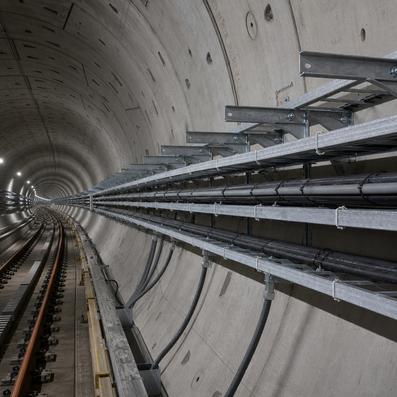
A cable ladder consists of two C-profile side rails joined by transverse rungs at regular intervals — typically 250 mm or 300 mm spacing — with the rungs resistance-welded or mechanically swaged to the rails. The open construction is its defining engineering feature.
The design logic follows the cables it serves. Heavy power cables — medium-voltage feeders, large cross-section power conductors — generate heat when loaded, and the open rung structure lets that heat escape continuously along the full run. The ventilated construction also gives installers lashing points at every rung, so cables can be secured at any point without drilling, and it keeps every cable visible for inspection and tracing along the entire route.
Structurally, the ladder behaves as a truss-like frame. Deep C-profile rails resist bending and twisting, which translates into longer allowable support spans and higher load ratings per section than tray members of similar weight. This is why ladders are the default choice for power plants, substations, heavy industry and, increasingly, data center power distribution, where long overhead runs of large cables must be supported without excessive support density.
Typical ladder specifications — using hot-dip galvanized steel as the reference — run from 200 mm to 900 mm in width, in standard 3 m and 6 m section lengths, with side rail heights of 100 mm or 150 mm and rung pitch of 250 mm or 300 mm. Load ratings are published per width, rung pitch and support spacing in accordance with NEMA VE 1 or IEC 61537 test methods.
What a tray-type system is
Tray-type members — solid-bottom and perforated — share the same side-rail family but carry a continuous or perforated bottom between the rails instead of open rungs.
The solid-bottom tray is a closed trough. It provides the highest level of mechanical protection for the cables inside, shielding them from falling debris, dripping fluids and casual contact, and it contains cable flames better in fire scenarios when fitted with covers and fire barriers. Its downside is thermal: heat from energized cables has no escape path except through the metal, so solid-bottom systems require conservative cable fill calculations and are rarely used for heavily loaded power circuits.
The perforated (ventilated) tray is the compromise: a bottom punched with ventilation slots that allows partial heat dissipation while still containing the cables. It is the workhorse for mixed power and control runs, balancing airflow with protection, and it is commonly used in commercial buildings, process plants and general industrial distribution where cable volumes are high but individual cable sizes are moderate.
Because tray members distribute load across a continuous sheet rather than discrete rungs, they are well suited to large numbers of smaller cables — instrumentation, control, communication and lighting circuits — where the cable count matters more than any single conductor’s weight. The trade-off is that the continuous bottom adds material, which makes tray-type systems heavier and, per meter, more expensive than an equivalent ladder — and that weight shows up in support requirements.
Head-to-head comparison
| Criterion | Cable Ladder | Tray (Solid/Perforated Bottom) |
|---|---|---|
| Structure | Open rungs between two side rails | Continuous or perforated sheet bottom |
| Heat dissipation | Excellent — open rungs vent continuously | Perforated: moderate; solid: poor |
| Cable access & inspection | Full access at every point | Requires removing covers; cable buried |
| Best cable type | Heavy power cables, large conductors | Many small/medium cables (control, signal, lighting) |
| Load & span | High load ratings, longer support spans | Moderate; denser support spacing needed |
| Weight of system | Lighter per meter | Heavier per meter (more material) |
| Relative cost per meter | Lower | Higher |
| Mechanical protection | Low (cables exposed) | High (contained within trough) |
| Fire containment | Requires covers/barriers | Better inherent containment |
| Typical environments | Power plants, substations, data centers, heavy industry | Commercial buildings, process plants, general distribution |
When to specify a cable ladder
Choose a cable ladder when the run is dominated by power cables and the priorities are heat, span and access:
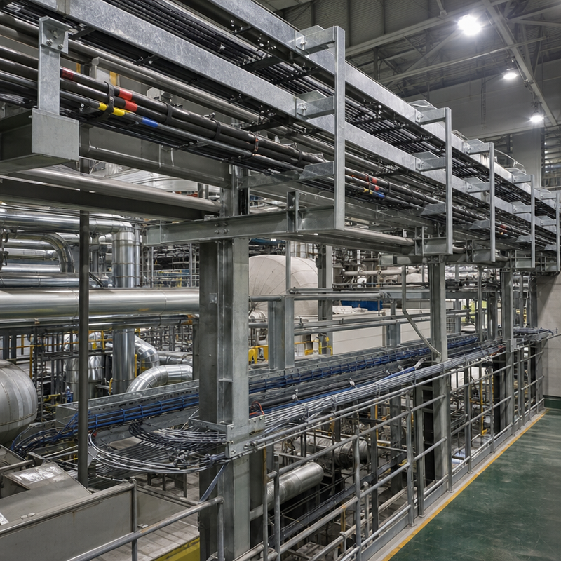
- Power plants and substations, where medium-voltage feeders and large power conductors run long overhead routes
- Data center power distribution, where high cable densities above racks demand heat dissipation and ventilated construction
- Heavy industrial facilities — mills, mines, oil and gas — where large cables and vibration favor a robust, open structure
- Any long-span overhead run where fewer supports mean lower installed cost
When to specify a tray-type system
Choose a solid-bottom or perforated tray when the run carries many smaller cables, or when protection matters more than heat:
- Commercial and institutional buildings, for control, communication and lighting circuits in risers and ceiling spaces
- Process plants, for mixed instrument and control cabling where containment and segregation are required
- Dust-prone or fluid-exposure areas, where a solid bottom shields cables from dripping or falling material
- Fire-sensitive routes, where solid-bottom construction with covers and barriers supports compartmentation
Common misconceptions
“A ladder can do everything a tray can.” Not quite. Ladders excel with power cables but offer no containment — dust, debris and drips reach the , and small control cables can sag between rungs if not continuously supported.
“Tray is always stronger than ladder.” The opposite is usually true per unit weight. A ladder’s truss-like frame carries higher loads over longer spans than a sheet-bottom tray of similar material.
“Solid bottom means the cables stay cooler.” No. Solid-bottom trays trap heat; the IEC and NEMA fill-ratio rules exist precisely because of this. If a run is heat-dominated, an open ladder or a well-ventilated perforated tray is the safer choice.
“You can mix them freely.” You can, with reducers and adapters, and many projects do — a plant may use ladders for its power feeders and perforated trays for its control circuits. The key is specifying each section for what it carries, and sourcing the transition fittings from the same manufacturer so the system remains mechanically and electrically continuous.
The specification bottom line
The selection rule is simple: let the cable decide. Heavy power cables over long spans with heat to shed point to a cable ladder. Large numbers of smaller cables needing containment and protection point to a tray-type system. And because both families must meet the same test and documentation requirements — NEMA VE 1, IEC 61537, with published load tables and material certificates — the supplier’s engineering documentation matters as much as the product type.
Manufacturers that build both families to the same standard, with matched fittings and complete documentation, make the decision easier: the system is specified as one coherent run, and the tray-versus-ladder choice is made section by section, on engineering grounds, rather than by habit.
Post time: Sep-07-2026